

CNC punching can produce repeated holes, slots, cut-outs and other features efficiently, but the process still depends on a design that suits the material, tooling and later fabrication stages. A drawing may look complete on screen and still create problems when it reaches production.
Many delays begin with small issues such as a missing material grade, an undersized hole, an outdated file or a feature placed too close to a bend. These details can lead to extra questions, drawing revisions, special tooling or a change to another cutting process.
This guide explains the most common sheet-metal design mistakes and how to avoid them before sending a project to a cnc punching service.
Leaving out the material, thickness or quantity
A sheet-metal drawing should identify the material before a supplier begins programming the job. Writing “steel” is rarely enough because different grades, thicknesses and finishes can behave differently during punching, bending and welding.
Specify whether the part requires mild steel, stainless steel, aluminium or another material. Include the grade when it affects corrosion resistance, strength, welding or appearance. The sheet thickness should also be stated clearly and use consistent units throughout the drawing.
Thickness affects more than the weight of the finished part. It can influence the practical size of punched holes, the clearance between the punch and die, the force required and the likelihood of distortion. A feature that works in a thin sheet may not produce the same result in a thicker one.
The required quantity is also important because it helps the supplier assess setup time, tooling and the most suitable process. One prototype, a short production run and a repeat order of identical panels may be approached differently. If future volumes are likely to increase, mention this during the first review so the design can be considered beyond the initial order.
If the supplier is expected to provide the material, state that in the enquiry. When customer-supplied sheet will be used, confirm that the material is suitable for the machine and whether additional sheet is needed for setup, testing or possible rejects.
Failing to explain the purpose of the finished part
A production drawing tells the supplier what to make, but a short explanation of the part’s function can reveal requirements that are not obvious from its geometry.
For example, a cover panel may need a clean visible surface, while an internal mounting plate may place greater importance on hole positions than appearance. An outdoor enclosure may require corrosion protection, and a component fitted near heat or chemicals may need a particular material grade.
Assembly details are equally useful. If a slot accepts a tab, a hole locates another component or two edges must align after bending, identify those relationships. This helps the fabricator understand which features are functionally important.
The intended environment can also affect the finishing process. Powder coating, plating, anodising and galvanising can change the surface or add a coating layer. If a hole, thread, mating surface or electrical contact must remain free of coating, that requirement should be discussed before manufacture.
This information does not need to become a long technical report. A clear note describing the component’s use, assembly and operating environment may be enough to prevent the wrong material or process from being selected.
Using Features That Are Too Small or Too Close Together
One of the most common design mistakes is treating hole and slot dimensions as independent of material thickness. In practice, a very small feature in a relatively thick sheet may not punch cleanly with standard tooling.
If a hole is too small, the punch may be exposed to unnecessary stress, the metal may distort or the finished edge may not meet the expected quality. Narrow slots and thin sections between cut-outs can create similar problems.
There is no single minimum hole size that applies to every project. The practical limit depends on the material, thickness, tooling, feature shape and condition of the equipment. Stainless steel, for example, generally requires different consideration from softer aluminium or mild steel.
When producing high-precision sheet metal parts, it may be tempting to make every opening as small and exact as the CAD model allows. A better approach is to define what the feature must do and ask the supplier whether punching can achieve it consistently. If a very small or unusual feature is essential, laser cutting, machining or another process may be more suitable.
Standard hole and slot sizes can be easier to produce when matching tools are already available. Before finalising a design with many slightly different dimensions, ask whether some features can share a standard size without affecting function.
Placing features too close to edges, bends or each other
Hole position matters just as much as hole size. A feature placed too close to the outside edge can leave a weak strip of material that deforms during punching or later handling. Closely spaced holes can also reduce strength or cause the sheet to distort.
Problems can become more noticeable when a row of perforations covers a large area. Removing material changes the stiffness of the sheet, so a panel containing many openings may not remain as flat as a solid sheet. The pattern, pitch, margins and remaining material should therefore be considered together.
Bends create another risk. A hole or slot positioned too close to a bend line may stretch, distort or move when the part is formed. The appropriate clearance depends on material thickness, bend radius, tooling and bend direction.
Instead of applying an assumed distance to every design, identify the final folded shape and ask the fabricator to review features near bends. Moving a hole slightly or changing the bend arrangement can be easier than correcting a component after it has been punched.
Sharp corners and narrow connections between features also deserve attention. Adding an appropriate radius or increasing the remaining material can reduce stress concentrations and make the component more practical to manufacture.
Supplying Drawings That Are Not Production-Ready
Submitting duplicate lines, open profiles or incorrect scales
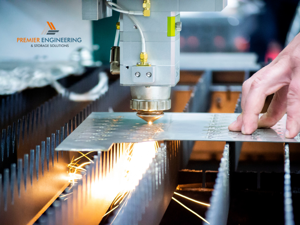
A clean drawing helps a supplier prepare the job without guessing what should be punched, marked or ignored. Problems often arise when a CAD export contains duplicate geometry, disconnected profiles, construction lines or hidden elements from an earlier design.
Duplicate lines can cause the software to interpret the same feature more than once. Open profiles may not define a complete cut-out, while overlapping shapes can make the required boundary unclear. Unnecessary layers and annotations may also complicate the programming process.
Scale is another common source of delay. A file may be drawn in millimetres but imported as inches, or exported at a reduced presentation scale instead of full size. One known reference dimension should be included so the supplier can confirm that the file has imported correctly.
DXF and DWG files are often used for flat sheet-metal profiles, although accepted formats differ among providers. A PDF drawing can accompany the production file to show dimensions, notes, tolerances and the intended appearance. The two files should agree with each other.
Before sending the design, open the exported file independently and check the geometry. Confirm that the part is full size, profiles are closed, repeated lines have been removed and only the required manufacturing information remains.
A cnc cutting machine follows programmed instructions accurately, but it cannot determine which conflicting line reflects the designer’s real intention. Clear input remains essential even when the production equipment is highly automated.
Sending conflicting dimensions or outdated revisions
Revision control is one of the simplest ways to prevent the wrong part from being produced. File names such as “final,” “final updated” and “latest version” are difficult to manage once several people have exchanged copies.
Give every component a part number and every approved change a revision. Show that information inside the drawing rather than relying only on the filename. When a new revision is issued, explain what changed and state clearly that the earlier version is no longer approved.
Dimensions should also agree with the digital geometry. If a drawn hole measures 10 mm but its annotation says 12 mm, the supplier must stop and ask which value is correct. Do not assume that a written dimension will always override the model or that the model will automatically override the drawing.
The same principle applies to quantities, materials and finishes. If the purchase order, email and drawing contain different instructions, production cannot proceed confidently.
Once the supplier has prepared programming or tooling, a design change may affect price and lead time. Send revisions before approving production and request written confirmation that the new version has been received. This creates a clearer record for both the customer and the fabricator.
Specifying Materials and Tolerances Without Practical Need
Material selection should begin with the finished part’s function rather than price alone. Strength, weight, corrosion resistance, weldability, appearance and finishing requirements all influence the appropriate choice.
Mild steel is widely used in general fabrication, but it often requires a protective finish where corrosion is a concern. Stainless steel may be selected for corrosion resistance, cleaning requirements or appearance, while aluminium can suit applications where lower weight is important. The specific grade still matters within each material family.
The phrase cnc stainless steel can refer to several processes, including punching, laser cutting and machining. Stainless steel is not one uniform material, so provide the grade, thickness and surface finish instead of using the general term alone.
Protective film, brushed grain and visible surfaces should also be identified. If a stainless-steel panel has a directional finish, the drawing should show the required grain direction. Nesting parts in the wrong orientation may create an inconsistent appearance across an assembled product.
Metal punching services have machine-specific material and thickness limits. A supplier that punches thin mild steel may not automatically be able to process every stainless-steel or aluminium grade in the same range. Confirm capability before selecting a material solely because it appears suitable on paper.
Applying tight tolerances to every dimension
Tight tolerances should be reserved for features that require them. Applying the same restrictive tolerance to every edge, opening and overall dimension can increase inspection, programming and production requirements without improving how the part works.
Begin by identifying the features that control fit or function. These may include mounting holes, locating slots, mating edges or clearances around another component. Apply an appropriate tolerance to those dimensions and use practical general tolerances elsewhere.
Remember that punching is only one stage of cnc sheet metal fabrication. Bending, welding, fastener insertion and coating can influence the final dimensions. A tolerance that is achievable on a flat blank may not remain realistic after several fabrication stages.
If the part must fit an existing assembly, provide the mating dimensions or a sample where appropriate. This gives the supplier more context than a collection of tight numbers without an explanation.
You should also distinguish between dimensional tolerance and appearance. A component can be within size tolerance and still show burrs, witness marks or surface damage that are unacceptable for a visible application. State any finish requirements separately and discuss which side of the sheet will be visible.
For high-precision sheet metal parts, ask how the nominated dimensions will be measured and at which production stage. This helps ensure that the drawing, manufacturing method and inspection approach are aligned.
Forgetting About Bending and Secondary Fabrication

Ignoring bend allowances and feature positions
A flat pattern is not simply the sum of the finished outside dimensions. Metal stretches and compresses as it bends, so the developed length depends on material thickness, bend radius, bend angle and the forming method.
Using an incorrect bend allowance can leave the finished component too long, too short or unable to align with adjoining parts. For this reason, the flat pattern should be prepared using information appropriate to the fabricator’s tooling and process.
A metal bending press also needs enough material for the tooling to grip and form the flange. Very short flanges, closely spaced bends or features located near the bend line can be difficult to produce as drawn.
Hole positions should be reviewed in the folded state as well as the flat state. A hole that appears clear on the flat pattern may distort during bending or become difficult to access when the component is assembled.
Bend direction must be unambiguous. Include suitable bend notes, angles and up-or-down directions, supported by a folded view where possible. If appearance matters, identify the visible face so tooling marks and grain direction can be considered.
When in doubt, provide the finished three-dimensional model and ask the supplier to confirm or develop the production flat pattern. This can be safer than issuing an unverified flat file based on general bend assumptions.
Designing the blank without planning later operations
Punching may be only the beginning of the manufacturing process. Fasteners, folds, welds, coatings, labels and assembled hardware can all affect the original design.
If a self-clinching fastener will be inserted, the hole must suit the selected fastener and sheet thickness. A generic clearance hole may not provide the correct fit. The fastener location must also allow room for insertion tooling.
Welded assemblies need suitable joint access and a plan for controlling distortion. Slots and tabs may help locate parts, but their clearances should reflect the cutting and welding processes. Drainage or vent holes may also be required for certain finishing treatments.
Coatings can build on surfaces and inside openings. This matters when a pin, bearing, thread or close-fitting component will be installed after powder coating or plating. Masking requirements and post-finish operations should be identified before quoting.
Planning the complete sequence also helps determine whether punching is the best first operation. A supplier offering several fabrication services may recommend a more practical order for punching, bending, welding, finishing and assembly.
Customers should therefore request a quote for the required finished condition, not just the flat blank, unless cutting alone is genuinely the full scope. This makes it easier to compare prices and lead times accurately.
Choosing the Right Cutting and Punching Service
CNC punching is often well suited to sheet-metal parts containing repeated holes, slots, louvres, knockouts or other features that match available tooling. It can also create some formed features that a cutting-only process cannot produce.
However, punching is not automatically the best method for every profile. Intricate contours, unusual shapes, small production quantities or features requiring special punch tools may be better suited to laser cutting. Thicker materials or three-dimensional features may require another manufacturing process.
CNC cutting services can include laser, plasma, waterjet, routing or other computer-controlled methods, depending on the supplier. Ask which process is being recommended and why it suits the material, geometry, quantity and required finish.
The most useful comparison considers the complete component. Punching may be efficient for repeated standard features, while laser cutting may offer greater flexibility for complex outlines. In some production environments, more than one process may be considered before the final method is selected.
Premier Engineering lists both CNC punching and laser cutting among its manufacturing capabilities. This makes it practical to ask the company to review the drawing and confirm which available process is appropriate rather than selecting one based only on a keyword or machine name.
Compare suppliers using the requirements of your project
When choosing a cnc punching service, begin with technical suitability. Confirm the supported material, grade, thickness and sheet size. Then ask whether the provider has suitable tooling for the required holes, slots and formed features.
If special tooling is required, find out whether it affects setup cost or lead time. For repeat production, ask whether the tooling and approved files can be retained for future orders.
Design support can be valuable when the drawing has not yet been prepared for manufacture. Premier Engineering includes design and prototyping within its published capabilities, alongside press-brake bending, fastener insertion, welding and finishing services. Customers should confirm the exact scope required for their project before ordering.
Quality requirements should also be discussed clearly. Ask how the first part is checked, how drawing revisions are controlled and whether any requested inspection or material documentation can be provided. Do not assume that every workshop follows the same process or includes the same records as standard.
Location may matter when samples, prototypes or large components need to be transported. Premier Engineering is based in Ingleburn in south-west Sydney, which may be convenient for businesses operating across the surrounding industrial areas. Even so, technical capability, communication, total scope and realistic lead time should remain more important than distance alone.
Knowing When to Contact a Sheet-Metal Fabrication Company
Request design feedback before approving the drawing
Contact a fabricator before the design is final when you are uncertain about feature size, edge clearance, bend position, material thickness or the most suitable production method. Early feedback is particularly useful when the component includes many perforations, short flanges, formed features or close-fitting assemblies.
A supplier can only give useful guidance when enough information is available. Send the current drawing or model and explain which dimensions are fixed and which can be adjusted. If a hole size can change slightly to match existing tooling, state that flexibility. If it cannot change because it fits another component, make that clear as well.
It is also sensible to request input when moving from a prototype to regular production. A design that is acceptable for one sample may benefit from standardised features, improved nesting or simpler fabrication when ordered repeatedly.
Premier Engineering can be contacted when a project requires a review of punching alongside its related manufacturing capabilities. The drawing still needs to be assessed before the company can confirm process suitability, production requirements or timing.
Contacting a supplier early does not mean giving up control of the design. It provides manufacturing information that can help the designer make a more informed final decision.
Provide complete information for an accurate quotation
An accurate quote should begin with the latest approved drawing. Include the part number, revision, material, grade, thickness and quantity. Identify the critical tolerances, visible surfaces and any grain direction requirements.
State every production stage that should be included in the price. This may cover punching, laser cutting, bending, fastener insertion, welding, machining, powder coating, plating, screen printing, assembly, packaging or delivery.
Provide a three-dimensional model where it helps explain the finished component, but include a controlled drawing for dimensions, tolerances and notes. If only a sketch or sample is available, ask whether drawing and design support can be quoted separately.
The required completion date and delivery location should also be included. If the deadline is fixed, explain why and ask whether material availability, special tooling or outsourced finishing could affect it.
Finally, review the supplier’s quotation for assumptions and exclusions. Confirm the material, quantity, revision, finish and delivery scope before approving the work. A clear exchange at this stage is far easier to manage than a dispute after production.
Most CNC punching delays can be reduced through better information and earlier manufacturing input. Practical feature sizes, controlled files, suitable materials, clear tolerances and consideration of later fabrication all help a project move from drawing to production with fewer interruptions. If any of these details remain uncertain, contact the fabricator before approving the final design.
